

Peristaltic pumps vary their flow rate by changing their rotor turning speed and by changing the number of rollers fitted to the rotor.
Part |
Definition |
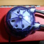
| Cassette | Removable shell that contains the tubing and rotor – during operation the tubing will need to be replaces as it wears. |
| Shaft | This shaft connects to the pump’s motor inside the red case to the rotor |
| Rotor | Contains a number of rollers (depending on head model clear, blue, green) which turn with the rotor squeezing the tubing creating a peristaltic pumping action. |
| Tie wrap knots turned to same direction | These wraps create a mechanical connection to the outside of the pump tubing. They lock into recesses in the cassette and prevent the tubing from ‘creeping’ along as the rotor’s rollers kneed the tubing. |
| Pump head Cassette + Rotor |
The cassette containing tubing and a rotor ready for fitting to the pump – Pump head. |
| Keypad/User Interface | This is where humans can press buttons to program and operate the pump. More details on the front panel. |
| Base | Base is mounted permanently on the pump. Receives the pump head which clips onto it. |
| Axle | The same item as the shaft. This end is formed as a flat blade which engages in the rotor – the rotor diagram shows the t shaped receptacle in the rotor’s centre. |
Peristaltic Output Tube Positions
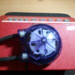
The NE-9000 family of pumps can have their output tubing orientated in four directions, Bottom, Top, Left and Right. When you are fitting your pump head, rotate the tubing to one of these four directions, and fit the head to the pump.
Output tubes to right of pump
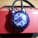
Output tubes to top of pump
Output tubes to left of pump
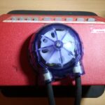
Output tubes at bottom of pump
See my other parts of posts:
Back to Pumps | Back to FAQs