Part Name |
Definition |
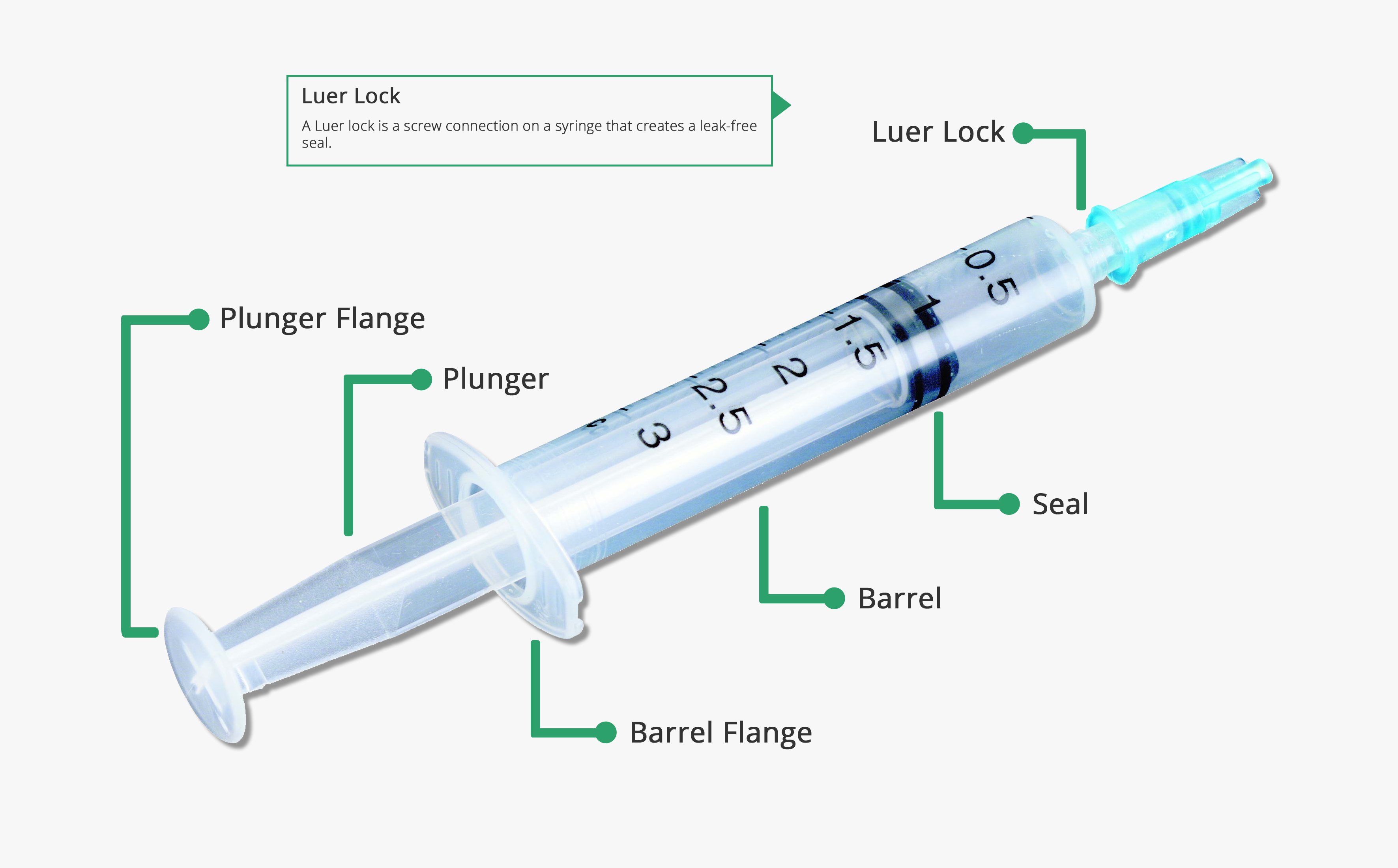
| Plunger Flange | The Plunger Flange bears the load of whatever is pushing the plunger. That might be your thumb or a syringe pump pusher block. The Plunger Flange is usually locked into the anti-siphon plate by the anti-siphon screw. |
| Plunger | The shaft that connects the Plunger Flange to the seal. The pressure applied through this shaft to the seal where it presses on the liquid in the barrel. |
| Barrel Flange | The Barrel Flange is located on the Barrel of the syringe. The syringe is supported here usually by a couple of fingers, or when the syringe is fitted to a syringe pump by the syringe retainer.
Pressure exerted between the Plunger Flange and the Barrel Flanges results in liquid being forced out of the syringe. |
| Barrel | Storage cylinder for the liquid which is to be dispensed. Pressure on the seal reduces the volume of the barrel below the seal expelling fluid. |
| Seal | Forms a liquid seal between the plunger and barrel. Slides up and down the barrel in response to the pressure on the plunger. In time can wear out and leak liquid. High pressure on the plunger can drive the plunger through the seal causing fluid leak. Some fluids may attack the seal and cause leakage. |
| Luer Lock | The output of the syringe is formed into a Luer Lock. The Luer Lock is a standardized screw fitting for attaching fittings to the syringe that will not ‘blow off’ when the liquid is under pressure. There is also a Luer Taper.
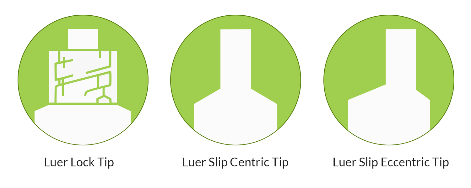
Luer-Slip fittings conform to Luer taper dimensions and are held by friction there is no thread. |
Types of Luer Lock
This diagram illustrates the three different styles of Luer lock. Their names are Luer Lock Tip, Luer Slip Centric Tip, and Luer Slip Eccentric Tip.

See my other parts of posts:
