
Can you make your own pump cables?
YES! – you can and this page contains the instructions on how to do it. To most people reading this page I’d like to say – don’t make your own cables. Read the section below – Why not just buy them?
This page contains instructions and diagrams to show you how to make:
- CBL-PC-PUMP connects your computer to your first pump and
- CBL-NET which connects between pumps. You will need 1 less than the number of pumps you plan to connect.
Why not just buy them?
T he total cost of a set of cables for one pump is approximately $US25 for one pump and for multiple pumps it’s $US25 plus $US2 for each extra pump.
If you order them today – you will have them in a few days as a general rule.
They will work. You will be finished in minutes.
So why not just buy them?
I don’t make a cent from selling cables but I do see days and weeks wasted waiting for home made cables to work.
Cable Identification Page See what the cables look like and identify them.
How hard is it to make your own pump cables?

I find it rather easy – I have all the parts and an electronics background and all the tools. I used to solder for a living. I have seen photos of cables people make. A lot of them are nice and very serviceable, but some of them – enough said.
- It will take you time, you will need to purchase parts – the correct parts, and the correct cable. You will probably do this for about $10US There is a list of parts on this page.
- You need to be able to solder and have a soldering iron and general electronics skills, wire striping, reading diagrams.
- You need a special crimp tool for the RJ11 connectors and possibly some instruction on how to use it. A crimping tools will cost say $US20.
- If you make a mistake and it doesn’t work – then you have to diagnose your issue and rework your cable.
I help a lot of folks making their own cables – possibly half of them give up after a week or two of emails and frustration and just buy the cables.
What cables do you need? One CBL-PC and how many CBL-NET?

First stop is to learn about wiring your pumps up. Take a look at this page on to build a pump network, work out what cables you will need.
There are two kinds of cables
- Pump-to-PC Primary Network Cable – you need exactly one of these. It’s part number is CBL-PC. It connects your computer to your first pump.
- Pump-to-Pump Secondary Network Cable – you need one to go between each pair of pumps you have. (One less than the number of pumps to be connected). It’s part number is CBL-NET.
The official cables look like this:
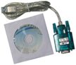
| USB-RS232 adapter |
USB Converter |
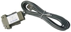
| Cable to connect from the COM port or USB-RS232 adapter to the first pump.
This assembly consists of a RJ11 female (socket)-Db9 adapter and an RJ11 to RJ11 cable. CBL-PC. |
 |
| Cable to connect from pump to pump. CBL-NET. | 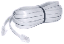 |
Pump-to-PC Primary Network Cable and RJ11-Db9 Adapter – CBL-PC
To make one set of these – an adapter and a cable, you will need
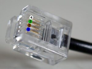 2 off RJ11 crimp connectors – 4 connector, they come in 4 and 6 connector styles. You need the 6 position style but with only 4 connectors fitted. A 6P4C. Look closely at the pump connector picture and you can see 6 position but only the middle 4 have gold connectors.
- You will need the special crimping tool- they are cheap. There is a photo on this page of this tool in action crimping a connector. The connector is not particularly visible as it is inside the tool.
- a length of 4 conductor telephone cable.
- A DB9 female to RJ11 female adapter kit – they are a few dollars. I get mine from ebay. This device is a rectangular plastic shell with a mounting for the DB9 plug, a few wires and the RJ11 socket. You have to insert the wires into the shell. There’s a picture below showing the correct colors and holes being used. You don’t have to have the adapter kit – you can solder to straight to a female solder type DB9F if you wish.

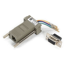
db9 to rj11 adapter kit
NOTE Think about buying a spare or two of each component – by the time you purchase this gear and wait for it to arrive …. Please consider the cost of a cable and adapter from your pump distributor – then it’s just plug and play – your not saving any? money really by making your own.
Here’s the wiring diagram for the adapter.
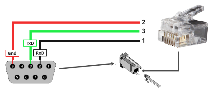
PC to Pump Cable Wiring Diagram
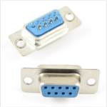
solder db9f front and back
There are Two Styles of DB9F
Note the adapter kit may come with wires and pins. The pins are inserted into the plastic block. Or it may come with a solder type of DB9F where the pins are already inserted into the plastic block and you need to solder the wires yourself. They both work the same.
Wiring it – CBL-PC
pump network connectors To Computer highlightedWe have two components to make:
- The adapter shell assembly– which includes wiring the DB9F to the shell’s RJ11 socket
- The “telephone cable” Which connects the adapter to your first pumps To Computer socket
Assembling the Adapter Shell
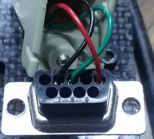
RS232toRJ11 Adaptor Showing Connections
The DB9F connector on the left is a female, and is illustrated from the Socket side – the side that receives the USB-RS232 connector.
This photo shows the rear of that female Db9 plug with the wires inserted. These wires are the internal cables for the shell. The end you can’t see is wired into the RJ11 socket in the shell. These wires come from the factory connected to the RJ11 and with the female pins already soldered on.They are from the left 2(black), 3(green) and 5(red).
If you look closely you can see the pin numbers are on the black plastic which holds the pins – the writing is very small and very hard to see. Use the photograph to guide you.
Your 4 connector cable will have black, red, green and yellow wires.
On the RJ11 end use – these are most likely already connected in the shell for you.
- black for pin 1
- red for pin 2
- green for pin 3
- Yellow is not used. Crimp it in the RJ11
On the DB9 female (pictured)
- black to pin 2
- green to pin 3
- red to pin 5
- yellow cut off. Yellow should be cut short it’s not used. Cut it off at the db9 end.
Simply push the pins into the rear of the socket as shown in the photograph. Assemble the plastic shell.
Making the “Telephone” Cable
- You will need:
- 2 off RJ11 crimp connectors
A length of “telephone cable” – this can safely be up to 25ft long (7 metres)
Learn more about maximum cable length and issues with electrical noise.
Crimp both connectors to the cable – make sure the order of the wires is the same in both connectors
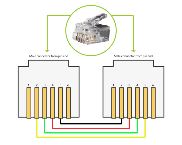
CBL-PC pin connections
Pump-to-Pump Secondary Network Cable CBL-NET
secondary cable
This is the cable that connects the first pump to the second, and then the second pump to the third etc. You will need
- 2 off RJ11 4 contact 6 position connectors
- a length of 4 conductor telephone cable
Let’s make the cable
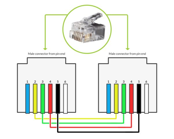
CBL-NET pin connections
This cable has what’s known as a twist. This is where the wires in the cable connect to opposite pins. Don’t be confused by this diagram – you don’t do anything other than reverse (twist the cable) when your crimp your second connector.
There are 4 wires in the cable coloured Black,Red, Green Yellow – they lay in that order.
- Crimp the first RJ11 connector on one end of the cable – black wire to pin 2 just like in the diagram left hand connector.
- Reverse the wire orientation in the second connector. i.e. make the green wire pin 2 instead of the black wire.
- Reverse the wire orientation in the second connector. i.e. make the black wire pin 4, Red pin 3, green, pin 2.”
Test Your New Pump Cable(s)
What you need next is a piece of software you know will work, and is free. You’re in luck! The try version of SyringePumpPro can be downloaded from this website for free. Once installed it will ALWAYS detect any correctly connected pumps. So go ahead, download SyringePumpPro and test your cable. If you have problems getting a connection to your pump, I have a heap of information on trouble-shooting in my FAQ-Connections section, and by all means please contact me and I will help you get your pumps up and running with SyringePumpPro.

Continuous Infusion Cable
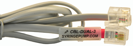
CBL-DUAL-3
I have included a photo of the continuous infusion cable. If you look closely at the image above, you will see the wire colors in each plug – this will let you make your own cable. If you compare the CBL-DUAL-3 Continuous infusion cable to a CBL-NET Pump-to-Pump Secondary Network Cable – you can see that they are wired the same. Really study that photo first! Then build yourself and CBL-NET!