
Diagram and brief explanation of a the parts of a syringe pump, and their purpose.

Part Name |
Description and Purpose |
| Anti-Siphon Plate Adjustment Knob | Finger screws are used to tighten the anti siphon plate against the syringe’s plunger flange. |
| End Plate | Provides mechanical support for the guide rods and lead screw. |
| Pusher Block | The Pusher block is driven by the lead screw and is supported by the guide rods and lead screw. Pusher block captures the syringe’s plunger flange. |
| Guide Rod (2 guide rods) | Guide rods prevent the pusher block from skewing under mechanical load and then causing a mechanical lockup on the lead screw. |
| Guide Rod Collar Clamp | A collar clamp allows operator to set a stall point on the pump by limiting the travel of the pusher block.
Used to prevent expensive glass syringes from being crushed when the pusher block is driven too close to the syringe retainer bracket and holder block. |
| Keypad/User Interface | Where humans can press buttons to program and operate the pump. VIDEO:More details on the front panel controls. |
| Syringe Clamp | Lift this clamp up and place the syringe barrel is underneath the clamp. Release the clamp to hold the syringe barrel in place. If there was no clamp a syringe might work it’s way out of the syringe holder bracket and pumping could cease. |
| Syringe Holder Block “V” Slot (on syringe holder block) |
This block features a large V shaped recess where a syringe barrel may be rested and supported. |
| Syringe Retainer Bracket | The syringe retainer bracket is used to hold the syringe barrel flange securely to prevent the barrel moving backwards and forward whilst pumping. This increases reputability and accuracy of the pump. |
| Syringe Retainer Thumbscrew
(2 on each side) |
These thumb screws secure the Syringe Retainer Bracket. |
| Drive-Screw | Commonly referred to as a lead screw. The pump motor (unseen) drives this precision threaded rod which passes through a brass nut block (unseen) in side the pusher block. This pushes and pulls the pusher block and thus the syringe plunger flange. |
| Anti-Siphon Plate | Prevents siphoning from a syringe. If a syringe is under vacuum pressure it’s plunger would tend to be withdrawn if it wasn’t secured by the anti-siphon plate. |
| Drive-Nut Button | Under this button is the brass nut block which is driven by the drive screw. The nut block is a mechanical protection device, designed to prevent mechanical and electrical damage to the pump, when a pump stall condition occurs.
Pressing and holding this button allows the plunger block position to be set at any position in the pump’s travel. It is normal to hear a click at the beginning of pumping as the nut block’s teeth re-engage the lead screw. If you stall your pump often it is the nut block that takes the punishment and will be worn out – you will need to have your pump serviced. |
| Power On/Off Switch | It’s a power switch! |
Front Panel Controls
The front panel has a number of buttons to operate the pump and an LCD display to indicate what the pump is doing. There are several LED indicators as well. To learn more about these controls and see a basic explanation video visit my Front Panel Control page.
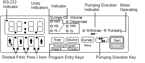
Pump Front Panel
See my other parts of posts: